
- All
- Stepcraft Accessories
- Stepcraft V1 Machines
- Stepcraft-2 Machine Assembly
- Stepcraft-2 Machine Operation
- UCCNC Installation
- UCNCC Operation
Aligning the Y axis can be the most difficult to setup, and may cause trouble homing the machine, moving to certain points at higher jog speeds, and running projects on the STEPCRAFT.
Machine is designed to jog at 100% speed as defined in the machine parameters for the full length of each axis. This speed is 50 mm/sec (3000mm/min) for the STEPCRAFT 2 machines.
If you are not able to jog at 100% it may cause a job running at a slower speed but more load to bind and/or lose steps as well. Losing steps is when the position of the machine is thrown off because the axis has been instructed to move and has not been able to complete the move, but the signal from UCCNC has been sent already.
It is also important to pay attention also to job setup because you could have a perfectly running machine but are overloading the machine due to the speeds and feeds set in the project. For example different materials will dictate the speed that the machine could cut at. There is quite a difference between cutting foam to cutting hardwood or even aluminum. Depth per cut is also a factor in the load the machine takes on while cutting. The general rule for woods is to start with half the diameter of the end mill as the depth per pass. Using a 1/8″ end mill set the depth per pass to 1/16″.
If you are first having trouble jogging the machine at 100% or homing look to this list of possible causes first, described in further detail below.
-Front and end plate alignment (DO FIRST if not done already) Step 15
-Gantry alignment Step 8.4
-Pulley and nut tightness Step 8.3
-Belt tension Step 8.5
-Lead screw alignment Step 8.2
-Roller bearing tension Step 3.3, 3.4
Where to start in diagnosing the Y axis alignment –
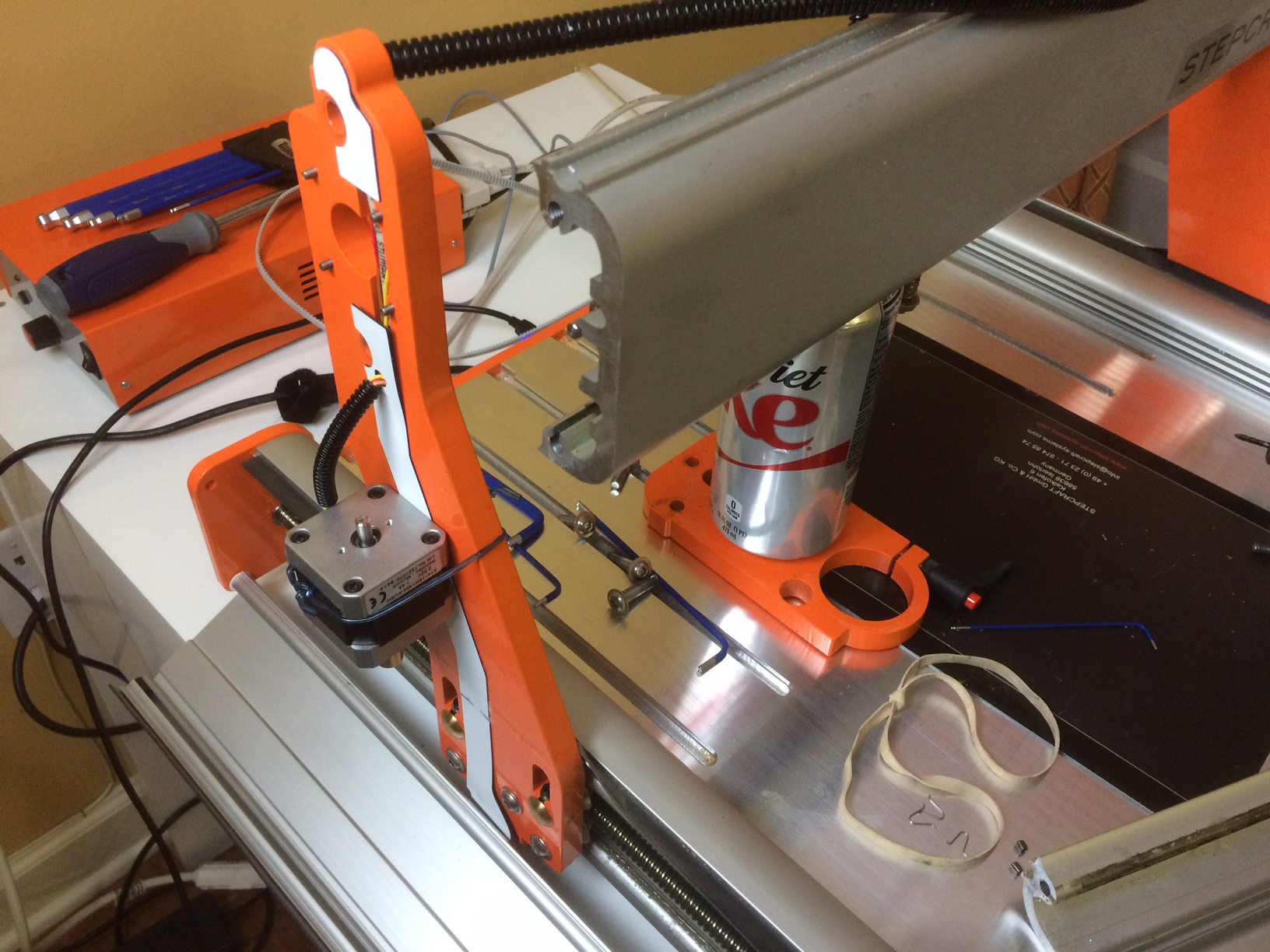
-Move the Y axis near the back of the machine and press in the Emergency stop button. Pressing in the emergency stop removes power from the motors so they no longer try to hold their position.
-Remove the belt cover by taking off the two 2mm allen screws.
-Try to move the belt by hand. It should be smooth and be able to move with one hand without the entire machine sliding on the table. I will usually get a good alignment on the Y axis just by testing it by hand. The machine is designed to operate in a precise tolerance, if it is difficult to move by hand it will not be able to run by the power correctly.
-Remove the belt by loosening the 2.5mm allen screw holding the tensioner in place.
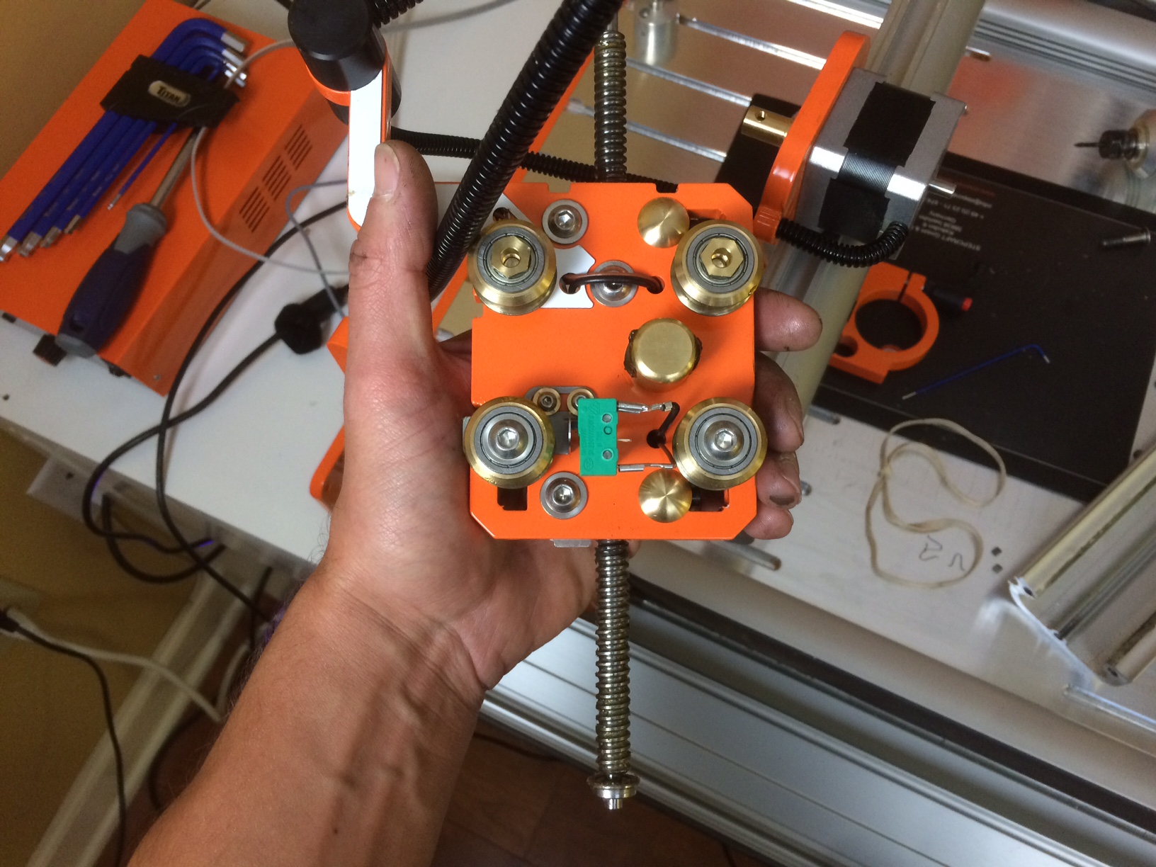
-Check pulley for looseness by holding lead screw and turning pulley. The pulley and lead screw should be move as one unit, you should not be able to turn the pulley and have the lead screw remain stationary. This could be part of your issue. While here test the tightness of the nut on the lead screw by loosening the 1mm set screw for the pulley, when it is slightly loosened it should be able to rock back and forth the nut should be just barely making contact with the pulley not heavily tightened down upon it.
-Check lead screw lateral alignment by pushing lead screw forward and backwards there should not be noticeable play of the pulley moving back and forth. This would indicate the lead screw isn’t fully seated, when this occurs it can affect the sides of the gantry causing a misalignment which can cause the Y axis to bind.
-Check the force needed to move each pulley, you only want to move each back and forth about 1/4 turn as moving too far will move the gantry out of alignment then it will definitely be more difficult to turn. You may feel one side is very smooth and the other is not. Or they both may feel tight to turn. If only one is difficult to turn concentrate efforts on looking at that side first.
-Check the tension of the bearings. Without taking apart more of the machine there is not an easy way to tell if they are too tight. You can tell if they are too loose by spinning the top bearings by hand or if you can rock the axis back and forth. If you suspect they are too tight loosen the 2.5mm allen screw then place a flat blade screwdriver on the screw and lightly tap the shaft of the screwdriver to move the bearing downward, releasing tension. DO NOT loosen the larger 4mm allen screw for the roller bearing assembly.
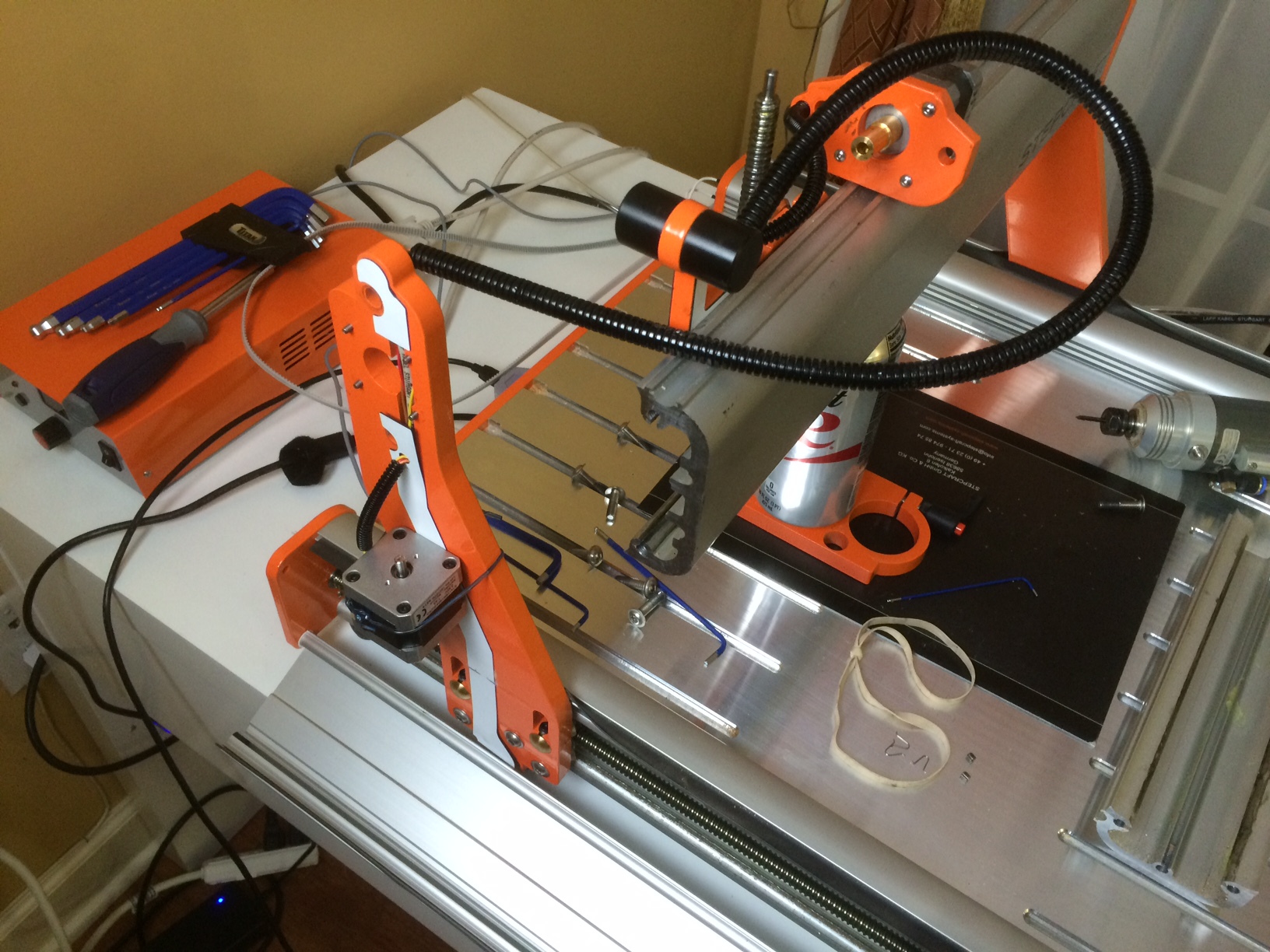
-Reset the lead screw and plate alignment. For this the gantry needs to be near the front of the machine. You could reinstall the belt and move it there by hand or use UCCNC to jog it forward as well. The rear plate of the machine should be tightened (in case you have had it loose in trying to align the machine already) with equal 1mm gaps between the plate and the Y axis extrusions. Follow Step 8.2 in the manual to make sure the amount of play the lead screw can move is equal between the bearing.
-Reset the gantry alignment. I will do this near the back of the machine where I can use two fixed objects of the same size between the gantry upright and rear plate. When using this method it helps keep the pulleys from moving when you install the belt starting on the side with the Y axis limit switch.
-The belt tension should be firm to press down on the belt but not take a lot of force to do so either.
These items are the main things to look over when trying to align the Y axis, there will sometimes be other things to look for as well that are best explained by contacting support directly. In some cases I will go through some of these steps more than once as changing one thing may effect another.
Once you have your Stepcraft machine built and UCCNC installed you’ll be almost ready to start creating. Now you are ready to tackle Step 15 which involves aligning your machine. During the assembly certain steps guide you to check and adjust free play of the lead screws and set gaps between the linear tracks and the various orange plates. These steps help to ensure that the machine aligns quickly and easily.
In Step 15 you are instructed to loosen the screws that hold the front and rear plates, X axis screws in the gantry, and the Z axis motor plate and tool plate. Use the homing buttons in UCCNC (the small red buttons next to home all in the upper right of the screen) to home each axis. This will bring an axis towards the limit switch, when it reaches the limit switches the machine will stop and reverse direction until it is off the switch. You can then run the machine to the other end of the axis to make sure it reaches and then tighten the screws when you are at the end of the axis only. For example with the Y axis tighten the screws for the rear plate when the machine the gantry is at the rear of the machine, then jog the machine to the front and tighten those screws. Sometimes you may have to tighten the front screws first or the rear first.
If everything has worked aligning each axis you are now ready to go, but if not then there may be additional work needed to get the machine aligned properly. The remainder of this FAQ will document the possible other items to check for each axis.
Z Axis:
- Lead screw alignment – Step 1.13 – Needs to be even or else tension may exist at the end of travel
- Tension of the motor connector to axial bearing – Step A.1 – There should be a small amount of oil between the axial bearing (part 22) and the connector (part 58). They should be installed to the point of the connector just touching the bearing. If pressed too tight this can cause resistance for the motor to turn.
- The alignment of the motor and tool plates are off – Step 2.1 – With these loose during the alignment they should come into the proper alignment but if they do not, set an even gap with the top and the bottom as shown in the green box in Step 2.1
X Axis:
- Lead screw alignment – Step 1.14 – Needs to be even or else tension may exist at the end of travel
- Tension of the motor connector to axial bearing – Step B – There should be a small amount of oil between the axial bearing (part 22) and the connector (part 58). They should be installed to the point of the connector just touching the bearing. If pressed too tight this can cause resistance for the motor to turn.
- The alignment of the X linear track to the gantry uprights. With the X axis carrying weight it is important to not that while the screws are loosened to align the machin the weight of the rack and Z axis carriage may pull down the axis. It may be necessary to raise the linear track by hand while aligning. As the axis reaches an end of travel it will pull itself into the correct location, but may bind beforehand if not raised slightly by hand.
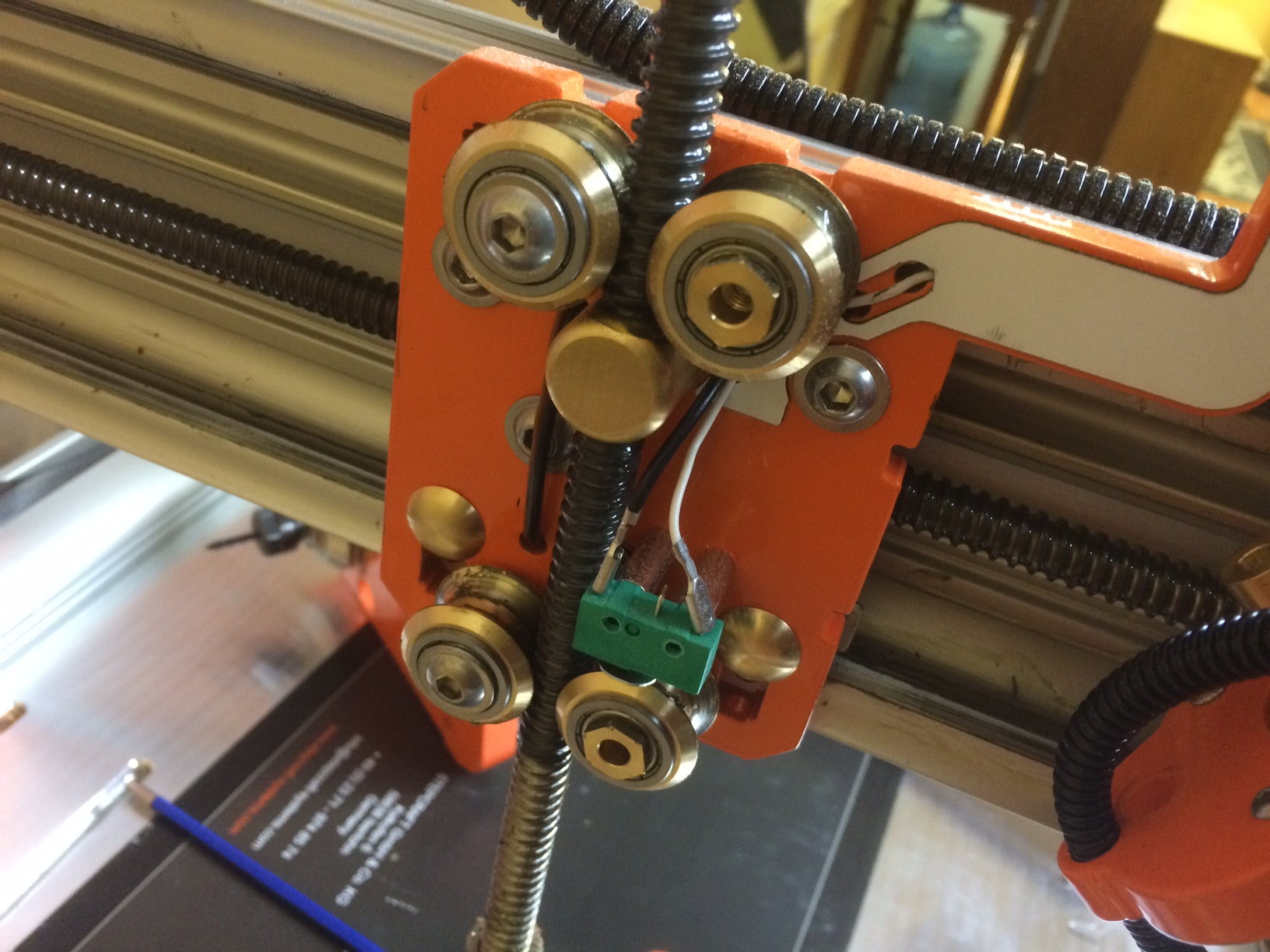
Y Axis:
- Gantry alignment – Step 8.4 – First ensure that the two gantry sides are in alignment. If one is further forward than the other the resistance can cause the machine to bind. With the drive belt off, check the alignment and then turn each pulley back and forth 1/4 to 1/2 turns. When the two sides are in alignment both should be easy to turn. If one side is more difficult to turn then investigate further onto that side.
- Lead screw free play – Step 8.2 – Make sure this is checked with the rear plate re-tightened (You may had had it loose trying to align) and the gap properly set as in Step 6.5. If you had the plate in its alignment here when you try to set the free play it will thrown off.
- Pulley install – Step 8.3 – The lock nut on the lead does not need to be tightened down tightly, the green inset box instructs to tighten the lock nut to just touching the pulley and the 1. indicated that you should be able to turn the pulley back and forth with the set screw slightly loosened. If the nut is too tight and you are not able to do this back it off until you are able, then fully tighten the set screw.
Outlined above are the assembly steps that coincide with the alignment. There may be other variables as well that could cause an issue, such as a bent lead screw or bent front or rear plate.
The Kress 800 Watt spindle has six power settings. These are the approximate spindle speeds per setting.
- 10,000 rpm
- 12,600 rpm
- 17,000 rpm
- 21,000 rpm
- 25,000 rpm
- 29,000 rpm
One of the questions we get asked often at shows where we present the machine is, “Does is include the software?” Which we generally reply saying yes it include UCCNC which is the machine control software or sometimes referred to as motion control software. So in this post I’d like to explain a little further what that means. UCCNC is what actually drives the Stepcraft machine. But just because it can make precise movements of the machine doesn’t mean it is very smart. It relies on a few things in order for it to work properly and get your project created.
Machine Parameters – During the install of the UCCNC software and following along Step 2.2 of the First Steps (UCCNC) Manual you should have installed the correct machine parameters for the machine you purchased. When this is done it creates a shortcut on your desktop that loads the parameters into UCCNC when it opens. This is the first step. The parameters include the travel distance for the axis, how they are connected to the machine, direction of travel, and how each motor has to turn to complete one unit of distance (mm).
Homing procedure (Reference Movement) – This is the next vital step to proper operation. You’ve loaded the correct profile so the machine knows how far it can move BUT it doesn’t know where it is until the reference movement is performed. On the upper right hand side of the UCCNC screen there is a button labeled home all. Along side are smaller red buttons which allow you to home axis individually. When you complete the homing procedure the machine now knows where it is, if the machine is properly aligned you can now move all the axis their full range of motion and because the machine parameters are loaded it knows when it needs to stop at the far end of the axis.
So now the machine knows how to travel and where it can travel. What happens next?
Load File – Now UCCNC is ready for a project. It reads a g-code formatted file using a “Mach 2/3 Arcs mm” post processor which contains instructions telling it where to move, how fast, etc. Properly creating this file is done using a CAM program. We sell CAM software from Vectric and feature articles and videos explaining it’s functions. We’ll get into that in another article. Assuming you have created a g-code file and you want to create it on your Stepcraft. The next thing to do is load the file using the load file button. When the file opens you will see a preview of the tool path in an overhead view by default. There are buttons along the left hand side of the screen that allow you to change the view. Below that you’ll see a window showing the g-code, this is for reference. You don’t need to know what the instructions are.
If you receive an error opening a file it may be that you are trying to open a drawing directly or Vectric project file. While the Vectric file does contain the tool path information you created, it’s basically in a different language. Saving the tool path(s) as a g-code file is translating that information into something that UCCNC can read.
Zero the work piece – Remember UCCNC doesn’t know everything, so it doesn’t know where your material is loaded, or where to start the project. When you began your project in the Vectric software the first thing you set up was the project size and the X Y Datum position. This sets a start point in relation to the project. Now match that with how the project is designed. The zero buttons in UCCNC have a zero all (if all axis are where they need to be) and individual buttons as well (if you need to adjust one value independently). To line set the Z height you can do it by eye depending on how precise your project needs to be, by using a piece of paper as a spacer lowering the Z axis until you can still slide the paper but feel resistance, or by using the optional tool length sensor. Remember when setting the Z height to slow down the jog speed for more precise lowering.
Cycle Start – Now everything should be ready to go. Clicking cycle start will begin the project, if you have a manual spindle you will need to turn it on before clicking cycle start, if you have an HF Spindle the spindle will start when cycle start is clicked.
Cycle Stop / Reset / Emergency Stop – If something is going wrong you have a few ways to stop the machine depending on your proximity to the machine and computer. The most urgent would be to press in the emergency button or click reset in UCCNC. If it is a more minor issue clicking Cycle Stop is optimal.
Here are some additional references to aid in the assembly of your Stepcraft CNC Machine.
1. Please inventory all parts before you start building your machine. While we take care at the factory to ensure all parts are shipped with all of the required parts to successfully build mistakes can occur. By checking for all parts any missing parts can be sent in one shipment at the beginning of your build instead of multiple shipments that would delay your build further. We’ll be happy to get out to you any missing parts so you can assemble your machine as soon as possible. You can email support@stepcraft.us for assistance.
2. Attaching the spade connectors to the limit and emergency stop switches may be difficult. The spade connector can be carefully opened up by using a small straight blade screwdriver. If too loose a slight crimp with pliers will correct this.
3. When setting up the track rollers you will want them to be set low, and then they will be adjusted to proper tension when they are inserted in the linear track.
This video shows how to set them up during assembly:
https://www.youtube.com/watch?v=6aG5ptrHDXc – Stepcraft Assembly Manual Step 1.8 – Track Roller Holder Assembly
This video shows how to properly set tension once in the linear track:
https://www.youtube.com/watch?v=zs7OTxZoik4 – StepCraft V1 Build Tips
3. There is a misprint in Assembly Step 3.2 – You should use part number 55 (track roller adjustable) NOT part number 54.
4. Bundle the ends of the Z and X axis motor wires. The wires will be passing through the corrugated channel and bundling eases these steps. Add an axis label for reference to aid when wiring them to the control board later in the build.
5. For customers who have purchased the tool length sensor you can view install and operation notes on our support website: http://www.stepcraftsupport.com/faq-items/install-and-setup-of-the-tool-length-sensor/
6. Your license file for UCCNC should be emailed to you with your invoice. If you did not receive a license file you can email support@stepcraft.us for yours. The license file needs to be placed in the C:\UCCNC folder in order for the software to read the infromation. Follow the instructions in the “First Steps (UCCNC)” Manual, along with our video at: https://www.youtube.com/watch?v=zSbNMaLLvV8 – Installing UCCNC for a Stepcraft CNC System
Resources:
http://www.stepcraftsupport.com – Support ticket system and FAQ Pages
http://www.youtube.com/stepcraftinc – Assembly and project videos
Working with Stepcraft machine you have two values the machine coordinates and the work-piece coordinates. The machine coordinates are the machine in the physical range of motion for the machine. When you perform the “Home All” when opening UCCNC it is doing this so UCCNC knows the location of the machine and controls it correctly. One item to note is the Y axis homes in reverse, so when the homing procedure completes the machine is at the upper limit of the Y axis. This is why it is required to have the correct machine profile loaded when running UCCNC
The images below show the difference in homing and moving the machine to X Y Z zero.
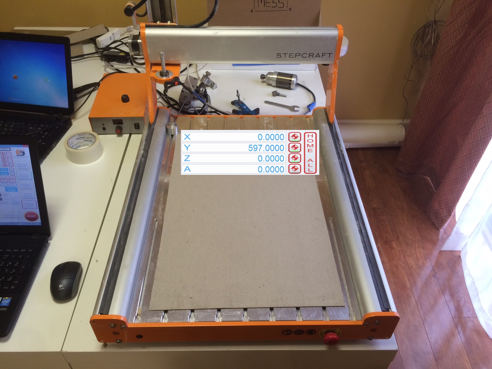
(Shown on a Stepcraft 600, the value will vary with your machine size)
This is with the machine at full zero.
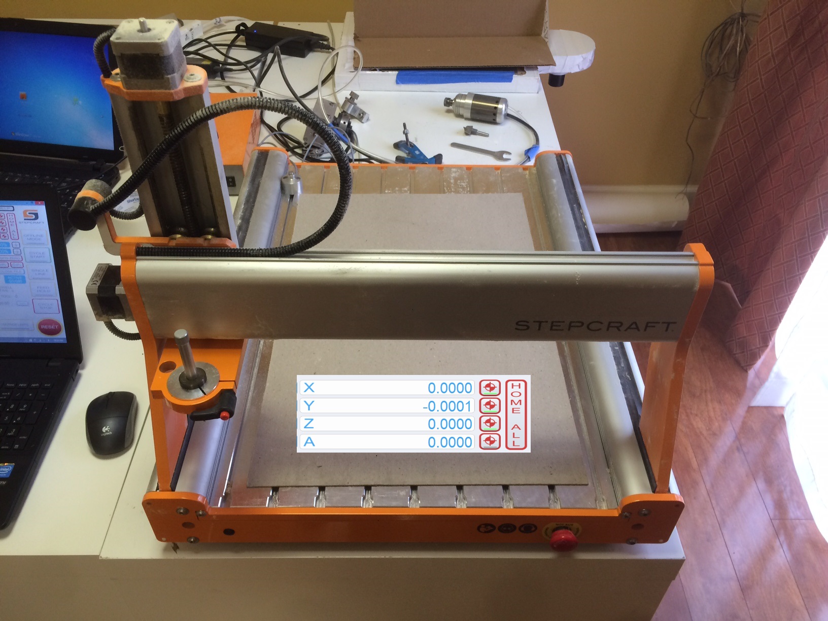
At this point moving the X axis to the right is X+, moving Y axis towards the back of the machine is Y+, and moving Z axis down is Z+
Familiarize yourself with this orientation of the machine. When you set up a project in your CAM software one of the choices will be the XY Datum Position or more commonly referred to as the start point. This is set so that when you start to machine your project you know it is starting in the correct spot. Depending on what your work piece is and how it is clamped to the table may sometimes cause you to change this.
For the examples here I have the start point set at the common lower left point.
Now the work-piece coordinates are set when you have a project ready. They are set by the blue zero buttons and the zero all button. When these are set UCCNC now knows where it needs to start. It will stop a job from starting if the job would run outside of the limits of the machine. If I am cutting something 10 inches wide on this model 600 I need to zero my X axis far enough to the left to allow the machine to safely travel 10 inches to the right. Same goes for the Y axis, if I try to set it too far back UCCNC will not allow the job to start because it knows it will run out of its limit. The Z axis also has an option for a start point and in most cases will be the top of the work piece. Make sure if you are opening a file someone sent that you know which Z origin is set. The axis can be zeroed individually or with the zero all. Generally I would move the machine to the proper X and Y locations then move the Z axis down and choose Zero All. Sometimes you may only need to change one of the start points, for example if you wanted to make another piece right next to the original you would only change the X zero.
In this image created a project of 10 inches by 10 inches and drew out the origin point and note on the X and Y zero. The full outline of the box shows what the “imaginary” blank slate of a 10×10 project actually looks like.

Now without changing the zero settings in UCCNC, I created a blank 10×10 project in Cut2D and added a Volkswagen logo to it. I used the center in workpiece option (F9 shortcut) to center the logo.
Now to run the project and see the results.

You’ll see in the image that it came out correctly as it was designed in Cut2D. The display is slightly different in UCCNC as it cuts off the excess in the display. Once a file is loaded in UCCNC and the zero point set a yellow dot will appear and show at the set start point. Manually jogging the machine the dot will move. This is useful to verify that the machine will not potentially hit any clamps or other obstructions that might be present. You can also use to this to make sure the material is going to cut where you want it to.
Knowing the project is where it should be you should be all set to choose “Cycle Start” and have a successful run.
After your Stepcraft machine is built there may be a need to access the XZ Connector to service parts of the machine. Which may seem like a quite daunting task but it is not that difficult. The key thing to make sure you have are ways to secure the Z and X motors, and to hold up the linear X track of the gantry. You will need to re-align the X and Z axes, and re-set the gantry alignment. Please read through the instructions to get a feel for what you will be doing before starting in.
Step One – Z Axis: Remove any tools in the tool holder and remove the three allen bolts holding it in place. Remove the set screw holding the motor connector to the lead screw. Now remove the two allen bolts holding the motor holder to the linear track. Take care as you are removing the last allen bolt as the track will now be free and may drop to the work bed. Remove the hose clip from the linear track and now you can secure the Z motor to the X linear track. The Z linear track is now free and you can pull it up to remove it. Now you have access to one side of the XZ connector.
Step Two – X Axis: First remove the toothed belt cover and toothed belt from the machine. Now remove the hose clips for the wiring on the X linear track. Remove the setscrew holding the motor connector to the threaded rod. Remove the four allen screws holding the X motor in place. Now you will be able to pull the X motor out, secure it to the side of the gantry. Remove the two allen screws holding the gantry side piece to the X linear track. Taking care with the wires that feed into the gantry side you can now turn the toothed pulley to move the one side of the gantry back. For ease of handling remove the X axis lead screw. Now with the lead screw removed and the gantry moved the XZ connector can be slid out. Take care with the wiring to let it be pulled. You may want to have a box or something you can place the XZ connector on.
Step Three – Re-assembly: Is reverse of the removal. Start with the X axis, re-installing the lead screw, line up the gantry, reinstall the motor and set screw for the lead screw and the allen bolts to hold the gantry together. For the Z axis slide the linear track back onto the XZ connector, re-connect the motor connector to the lead screw screw and the allen bolts to hold the motor holder to the linear track, and then re-install the tool holder plate. You will need to re-measure the gantry distance to re-align before re-installing the toothed belt.

If you have used the 4th Axis rotary mill and notice your project come out inverted you will need to update the settings in UCCNC.
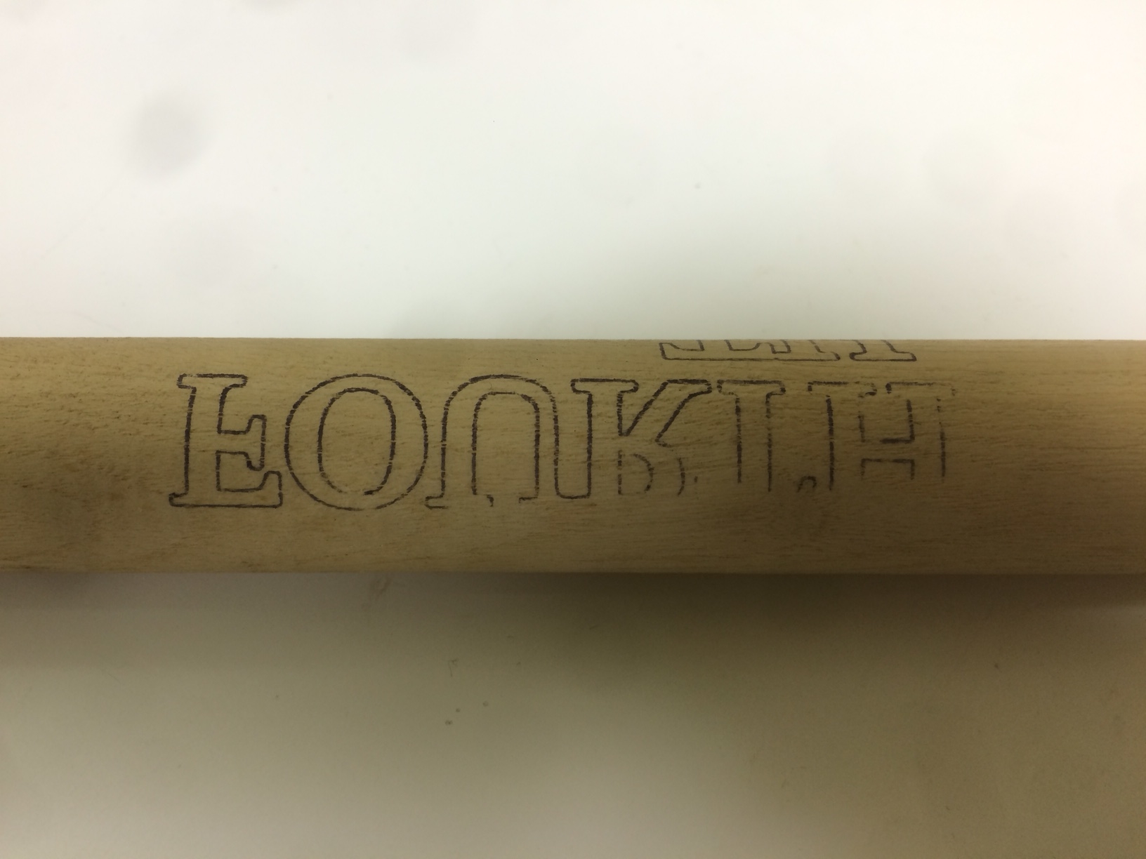
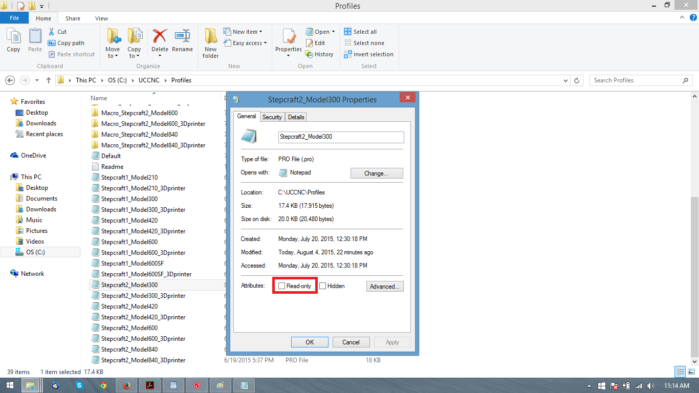
In order to be able to save the changes to you Stepcraft profile in UCCNC you first need to make sure the profile file is not set to read only. If you have previously installed the tool length sensor you would have verified this during the install already. If you have not open Windows Explorer and navigate to the C:\UCCNC\Profiles folder find the .PRO file for your machine, right click and choose properties, make sure the box marked read only is NOT checked. IF you made a change click apply, then OK.
Now you can open UCCNC through the normal profile shortcut, when UCCNC opens go to the Configuration tab, Axis setup, and A Axis. You will see “Dir pin:” in the list, to the right check the box for “Active Low” then click apply settings, then save settings.
This will now save to the profile so it will be the same when you open UCCNC again.
The Repetier-Host program ships with the 3D print head attachment and is used in conjunction with a slicing software that is built into it to prepare 3D models for printing. If you have drawn a 3D model yourself or downloaded one from online (http://www.thingiverse.com or various other sources) you will notice it is an STL file. Repetier-Host will load the model into a graphical work space in which you’ll be able to move and rotate the piece if needed.
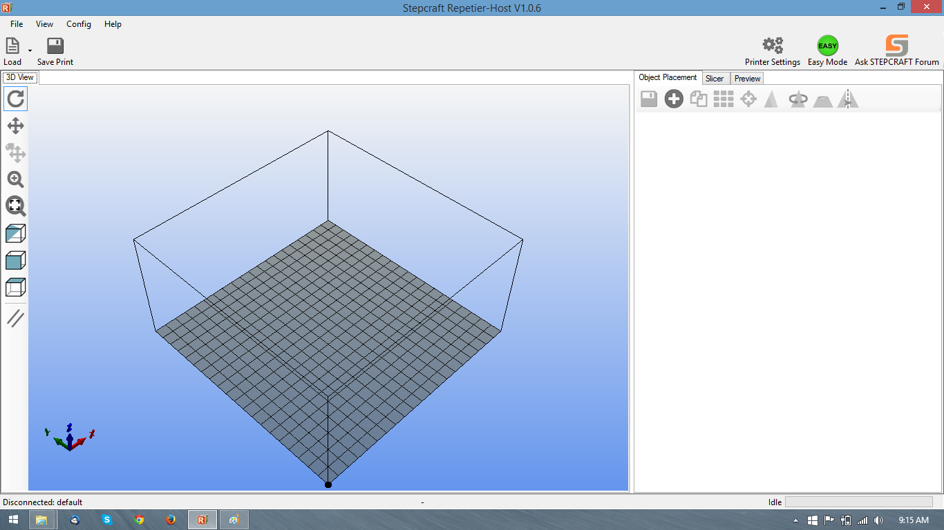
Here is the main screen zoomed out, the black dot is the zero point for the project. So when an object is placed you’ll want to place it close to this point.
Click on the load icon near the top left corner of the screen. You can now choose which 3D model you would like to load into the work space.
By default the object is placed in the center of the work space.
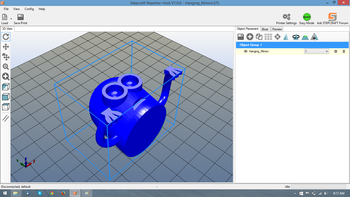
To move the piece I can click on the Move Object button which shows four arrows with a small truck and then click and drag the object to where I want it closer to that black dot.
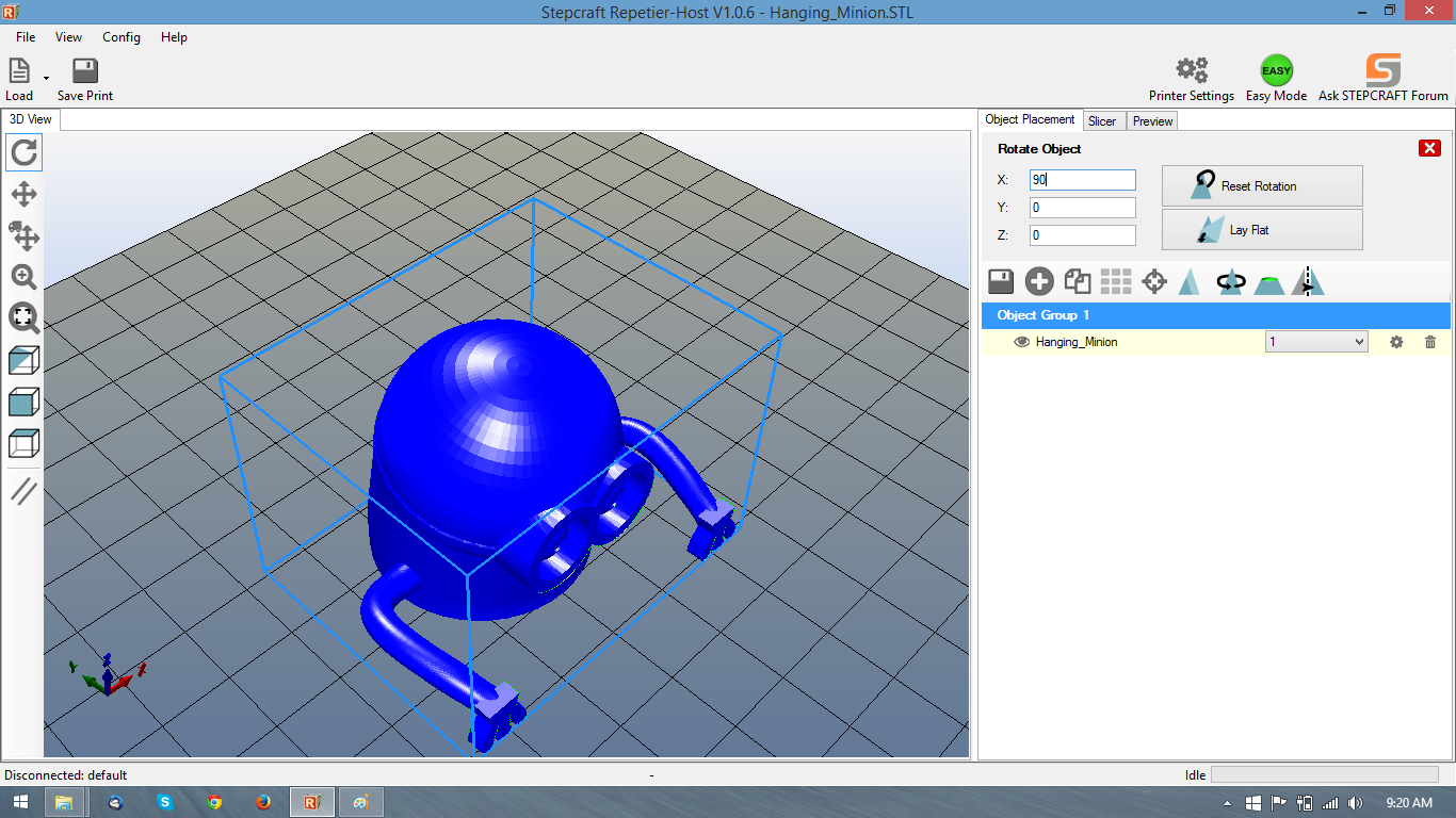
In the case of this model, I also need to rotate it to help make it print easier, the way it imported would make for a difficult if not impossible print. Since the first layers and only adhesion to the bed would be a small section of the cylindrical base. So I am going to click on “Rotate Object” towards the right hand side of the screen. This will give me choices for which values I want to rotate. In this case I am rotating the X value 90 degrees. Now standing up it will be easier to print, the only overhang will be around the eyes and arms instead of nearly the whole model.
Now I am going to click on the “Slicer” tab on the right hand side of the screen. When his comes up you can slice the model by hitting the “Slice with slic3r” button or configure the slicing, filament, and machine settings before hand. Clicking on configuration will bring of the settings.

In the configuration screen there are three main section, Print Settings, Filament Settings, and Printer Settings. You will generally be in the Print settings the most of the time adapting print settings for the different work you may be doing. Filament settings will allow you to adjust the extrusion rate and the true thickness of your 1.75mm PLA. Printer settings will allow you to change settings of the work space and parameters of the the g-code exportation.

Layers and perimeters will be one of the two sections you’ll be in most. You can change the layer height (up to the diameter of the nozzle) and the first layer height which to provide a good base you want to be at least .3mm. Running a smaller layer height will provide a more precise print but will take longer to complete. Perimeters are the outside layers or outline of the part. You want two perimeters at a minimum. If for example you are creating a hollow part you may want more perimeters. Solid layers will be how many layers at the top and bottom of the part will be solid faces. Making a part to pass through you would change these to zero.

The Infill settings determine how much of the inner section of the model will be filled in. You may need a solid part so you would choose 100% infill. But generally you would be choosing 30% and less. The pattern can be changed as well. If you are printing a model found online sometimes the creator will specify the amount of the infill needed. The material you use may allow you to change the infill amount as well.
Once you have settings chosen, click the save icon and then close the configuration page. You will be ready to slice the model now. Click the “Slice with Slic3r” button and the program will create the layers and g-code.

The completed slice will give you a print estimate time, filament needed, and total layers. On this screen too you can view individual layers to make sure things appear as they should. You will be able to see the infill amount and get a feel if you need more or less.
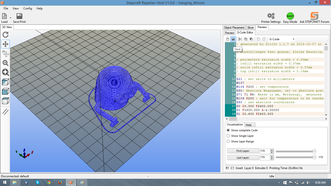
Click over to G Code Editor and near the top will be a save icon to save the project to a g-code file ready for UCCNC. Remember to open UCCNC under the profile link for “…_3D printer”, load the file, extrude some material via the A+ (up to 20% jog speed) until an even extrusion is coming out and then you’ll be ready to start printing.
Look for a full video coming soon.
This FAQ was created to help show the use of the Support Ticket system. If you have not already emailed support and gotten login information, follow the steps in “Option 1:” it is an easier and more customized way to begin using the ticket system.
Option 1: If you have NOT already emailed support and received login information for the ticket system go here to register http://www.stepcraftsupport.com/support-2/#/home This will bring to to a registration page. You can choose a username, your first and last name is preferably for us to look up your customer information with and enter your email address.
You will receive an email with a link to follow to set your password. The system will automatically fill in a secure password, but you can choose to overwrite the password and select your own. Then you can return to the ticket system and use the “Create new ticket” button to create your support ticket.
Option 2: If you have emailed support (support@stepcraft.us) you will have noticed that your message has been automatically turned into a support ticket and you’ve received a few emails back (*As of 9/10/15 possibly some duplicates as well) When emailing or creating a ticket please be descriptive yet succinct in the title of your email as that becomes the ticket. While something like “Hello Stepcraft” is a nice gesture, it makes it a little difficult for support to jump between tickets and remember the subject matter we are working with.
Here’s an example sent via my webmail client and the reply back:

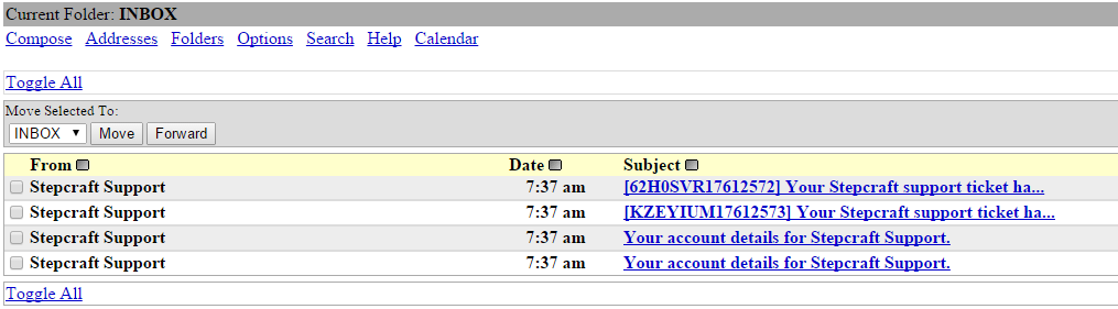
If you see these duplicates, follow the second email created via time. Following the first, you may get an error saying that the password you copied is incorrect. If that is the case check the other email and use that password. *This is a known issue and being worked on currently.
Logging in will bring you automatically to the ticket page where you can see your tickets. Pictured here a response has already been made from the support department.
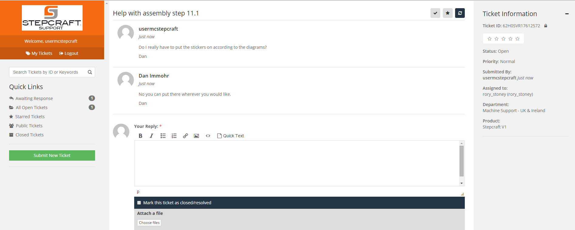
Depending on the type of question and answer received you may close the ticket if satisfied, answer any additional questions from support about the issue or leave it open. Support will close tickets periodically if there are no responses back in a reasonable time or if the issue is settled. You have the option to re-open a ticket by clicking the green folder and then add new comments.
If you are curious about some of the configuration and features of UCCNC there is a comprehensive manual located in the installation directory.
UCCNC_usersmanual.pdf is located in the the C:\UCCNC\Documentation folder.
If you happen to be away from the computer where UCCNC is installed you can also download the link from the manufacturer at http://www.cncdrive.com/UCCNC/UCCNC_usersmanual.pdf
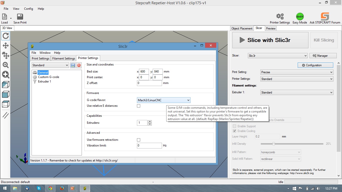
If you run across the issue of slicing an STL, exporting the G-Code, opening in UCCNC, and starting the print, only to have nothing come out of the print head. A setting in the Slic3r configuration may be to blame. Just as you need to choose an appropriate postprocessor when exporting toolpaths for a milling job, the correct G-Code Flavor needs to be set.
The setting chose should be “Mach3/LinuxCNC” other settings may run the machine differently or in the case of material not extruding change the A axis to E axis, which the machine will not recognize.
Click on configuration in the slicer tab on the right side of Repetier, then go to the Printer settings tab. Make sure it is set correctly if not change the setting and click the disk icon to save the setting.
You’ve opened UCCNC, pressed the reset button and move over to the jog controls or home all, and the machine doesn’t move. What now?
Which icon did you open UCCNC from?
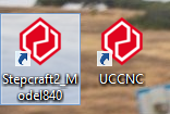
UCCNC should be opened from the icon on the left. The profile installed during setup. If you do not have an icon like the one on the left you will need to go back and run the screensetinst.exe file from the “Stepcraft” folder of the UCCNC install disc. You do not have un-install UCCNC for this work.
When you run the screensetinst.exe you will select what machine you have. In this example an Stepcraft 2 Model 840 with the 3D print head, so you would select the normal profile and the profile indicating 3D printer.
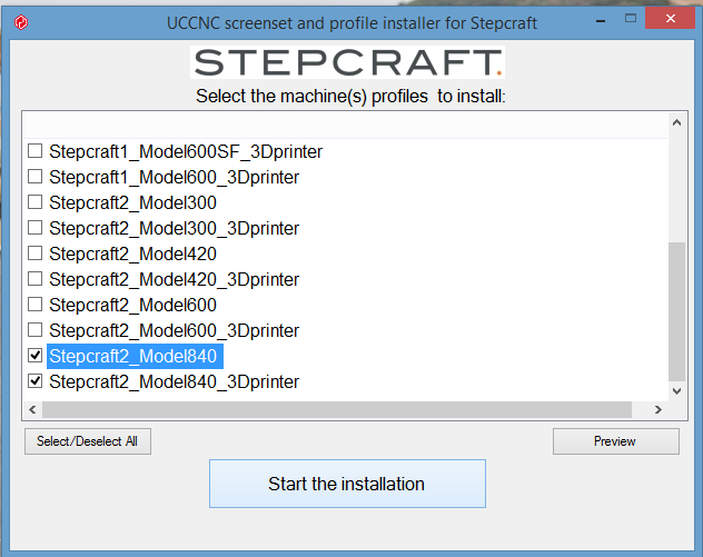
Once you have that completed you should be able to move the machine. It may stop before the end of travel if the machine is not homed. Click home all, and wait for the machine to finish, then you’ll be able to move the full range of movement for your machine.
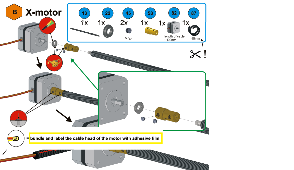
A few comments have come in regarding labeling and bundling of the motor wires. It is a small note in the manual that is easily overlooked. On the explanation of symbols page at the beginning of the manual shows an icon for labeling the wires. But when it is shown in Assembly steps A and B it is often missed. The reason for it’s note is two fold.
1. Bundling the wires at the end will make it significantly easier for it to route through the flexible hose later on in assembly.
2. So you will know which set of motor wires is which when you are wiring the control board near the end of assembly.
In this picture I transposed the text from earlier in the manual with the symbol you’ll see on the assembly step.
A heated bed can help but working with ABS in general is challenging. You end up with a lot of curling issues with larger parts. We have successfully tested the Stepcraft machine with ABS using a slurry of ABS mixed with Acetone and then brushed onto the bed. This worked very well for us. PLA is more common now and the new custom PLAs give you strength, flexibility and even conductiveness. All of which do not require a heated bed.
Another note on 3D printing… we have seen varying results from one spool of filament to another. As an example, we have two brand new rolls of PLA (white and Black) and the white printed fine at 185 degress but the black needed to be raised to 195 to get a good quality print. So some experimenting with various filaments, temperatures and slicer settings can help optimize your prints, not just with the Stepcraft, but with other printers as well.
We read a lot of comments with machine owners stating that they need to cut the M6x10 screw (part #41) on assembly step 1.4 of the manual to prevent the lead screw holder (part #59) from not tightening. The fact is that the design of the brass lead screw holder is such that you can apply a lot of force when tightening the M6x10 screw until it is completely tight without the need to cut or shorten the screw. You MUST use an L Shape Allen wrench to be able to apply the force to fully tighten the screw.
The Tool Length sensor is a great addition to your Stepcraft 2 machine, saving time in zeroing the Z axis. There are a few steps to getting the sensor installed and configured properly.
1. Connecting to the mainboard:
Remove the Rubber plug on the front end plate of the machine and run wires inward through the chassis. Run the wires along the channel and through the grommet the X and Z wires are run. Connect the sensor wires to the mainboard in the two open positions between the emergency stop switch wiring and the X/Z end switch (Refer to the manual section 9.6.) Leave enough slack to be able to move the sensor throughout the work area.
2. Replacing the Macro file:
UCCNC needs instructions to be able to properly use the sensor. Download the replacement M31.txt file (listed below) to the machine profile macro folder. For example for a Stepcraft 2 Model 300 the folder is C:\UCCNC\Profiles\Macro_Stepcraft2_Model300 If you have a 3D printing head and plan to use the sensor with that as well make sure to copy to the 3D profile folder as well. You will need move the existing file first as it is set to read only and will not let you successfully copy the file otherwise.
Download the latest macro file here: M31.TXT – Right click and save file. Save as M31.txt
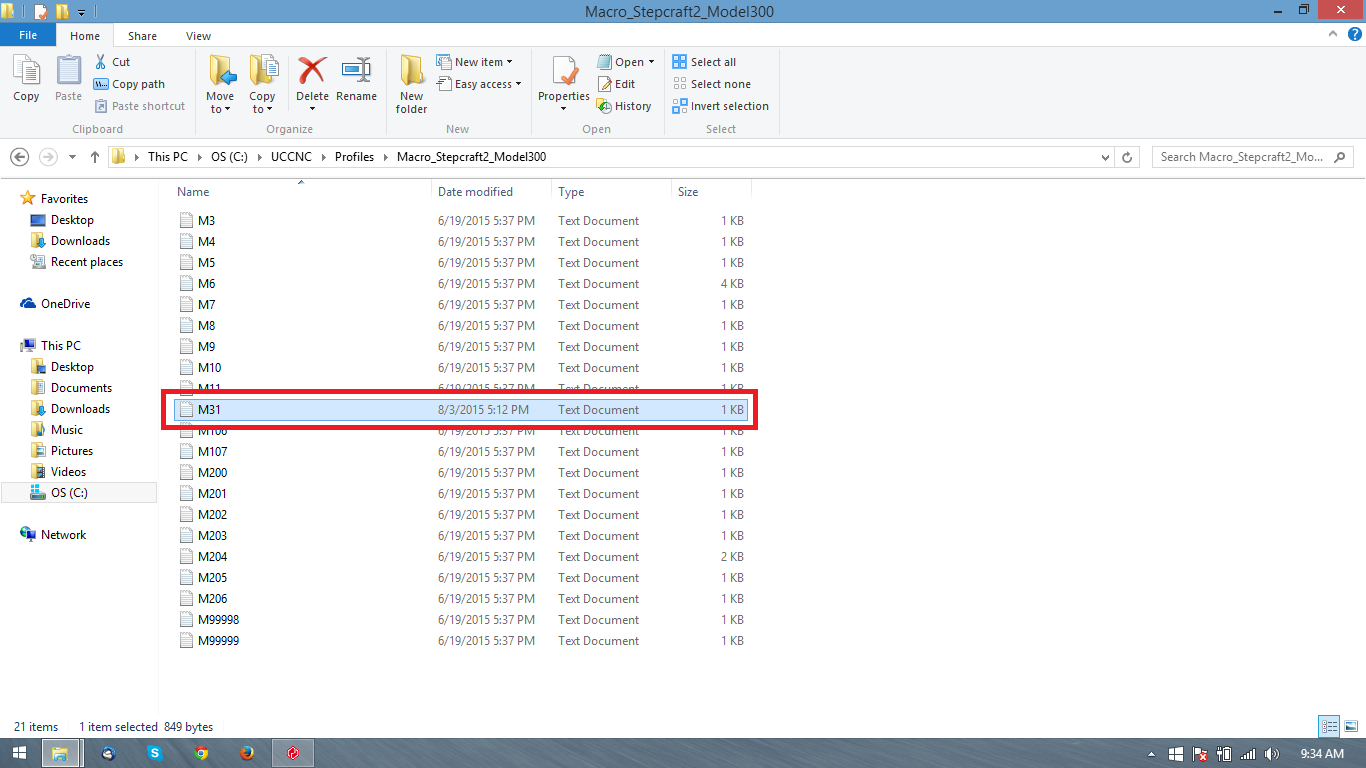
*Note: Opening the M31.txt will allow you to fine tune the height based on personal preference. Edit the newZ value (default 33) adding to the value to lower the Zero height. Since the setup will be separate for the 3D printer profile, you may want the print head slightly higher for 3d printing to avoid dragging.
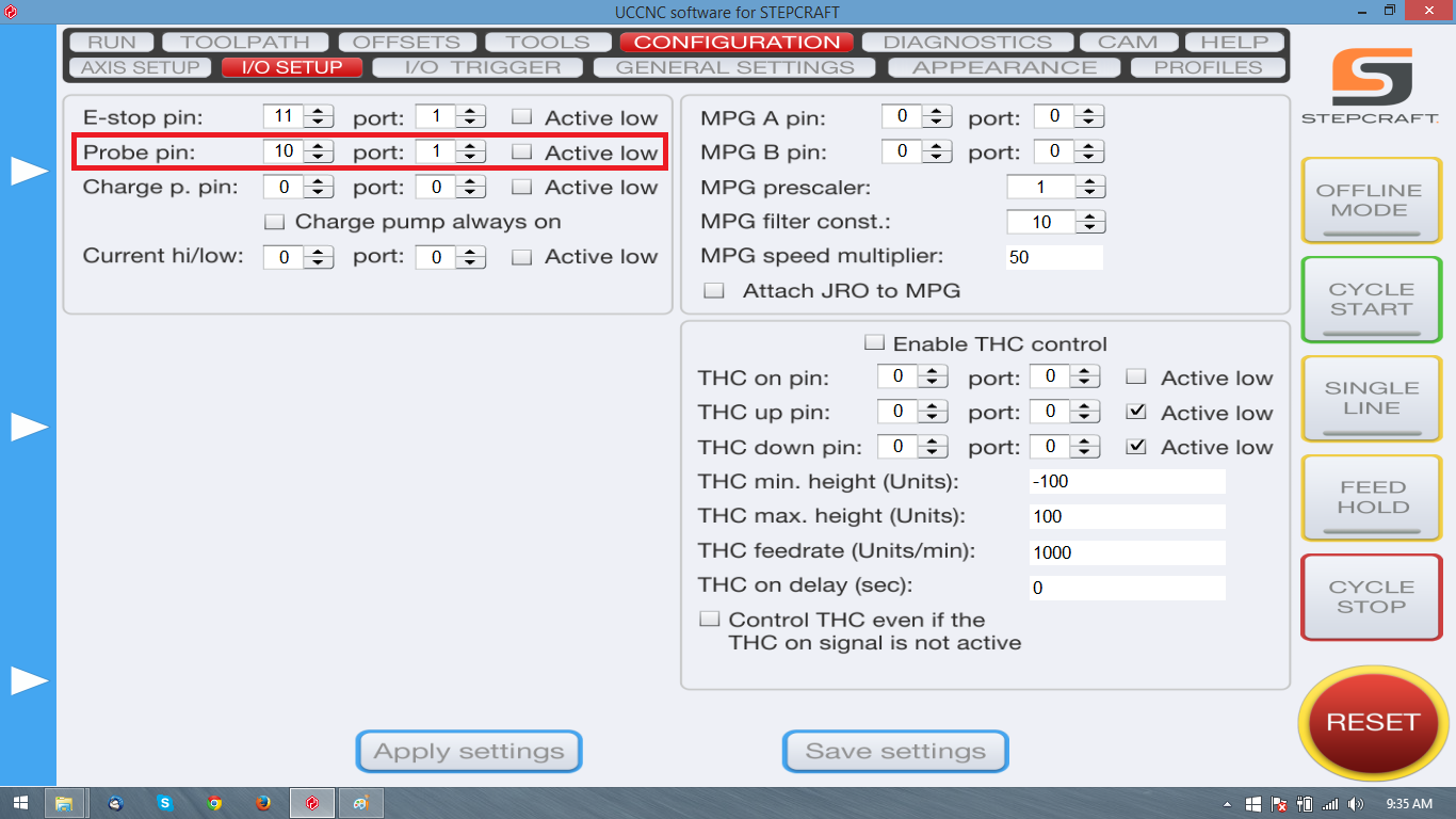
3. UCCNC Setup:
Now we need to edit the profile for the machine so that it knows the tool sensor is connected. In the is C:\UCCNC\Profiles\ find the .PRO file for your machine. First right click on it and choose properties. On the properties box there will be an option for read only, make sure that box is not checked. Click apply and close the window. Now when you change the setting in UCCNC it will be able to save and be stored for each time you open UCCNC.
Go to the configuration tab and I/O setup from there. You will see the choice for “Probe pin:” change that to 10, and “Port:” to 1. At the bottom of the page click Apply settings, and then Save Settings.
4. Verify switch function and setup:
Almost there, to verify the switch is operational and that it is properly configured open UCCNC click on the diagnostics tab. Press the sensor switch directly and you should see I10 and Probe light up in green. I10 is showing that the switch is working and Probe is showing that it is correctly configured.

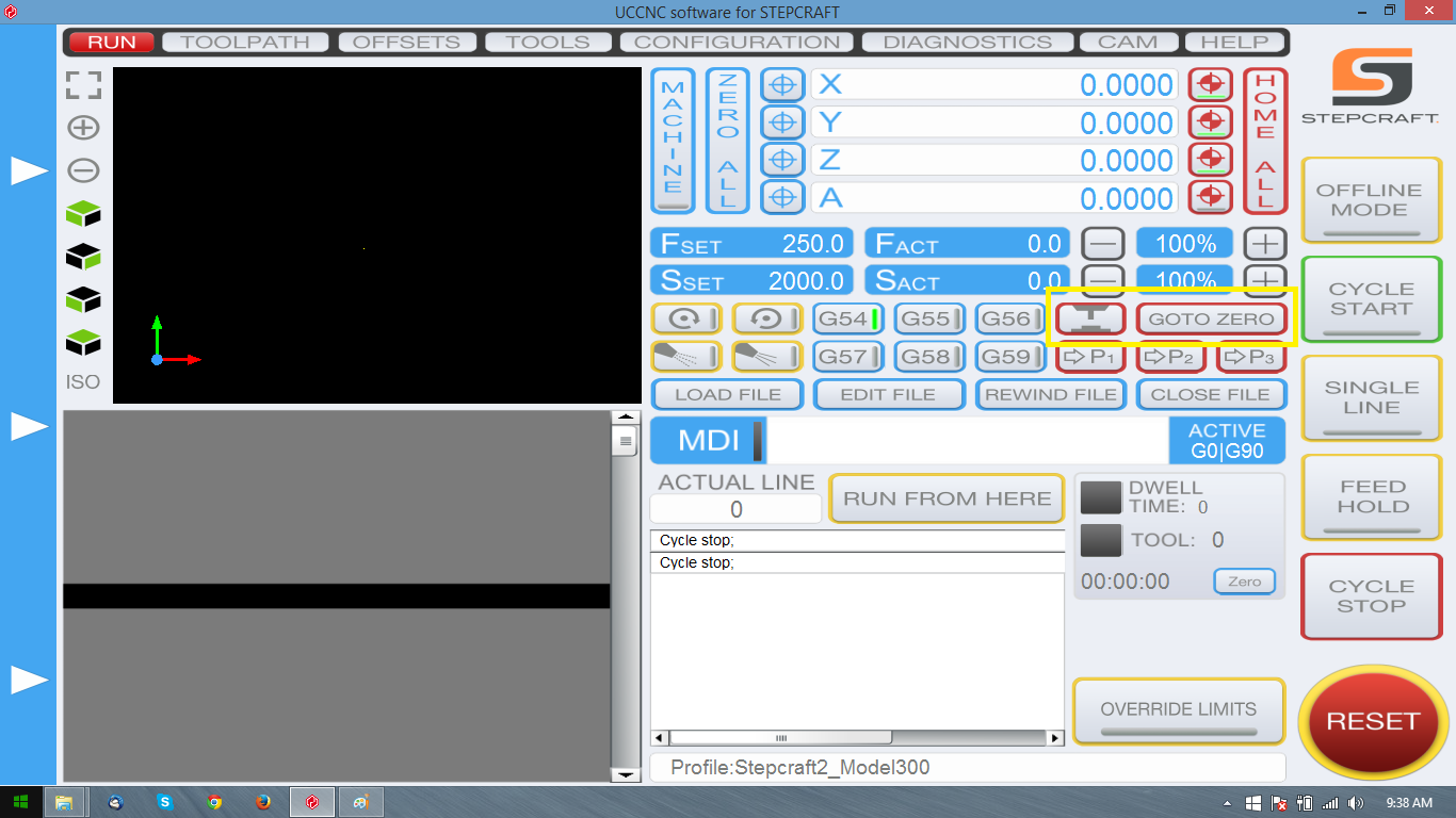
5. Using the sensor:
After homing your machine setup your machine with some test material and place the sensor on top. Move the axis over the sensor and zero all. Now press the tool probe button from the main screen. The Z axis will lower slowly until it contacts the sensor. It will then retract and calculate the Z zero taking into account the height of the sensor. Move the sensor out of the way and you can now click Go to Zero. The Z axis will lower to the calculated height for the work material.
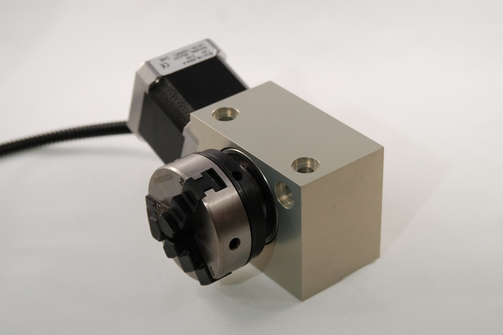
Stepcraft has designed the Rotary 4th Axis to dramatically increase the flexibility of the Stepcraft machines, allowing you to rotate a part and mill multiple sides without having to fixture the part for each rotation.
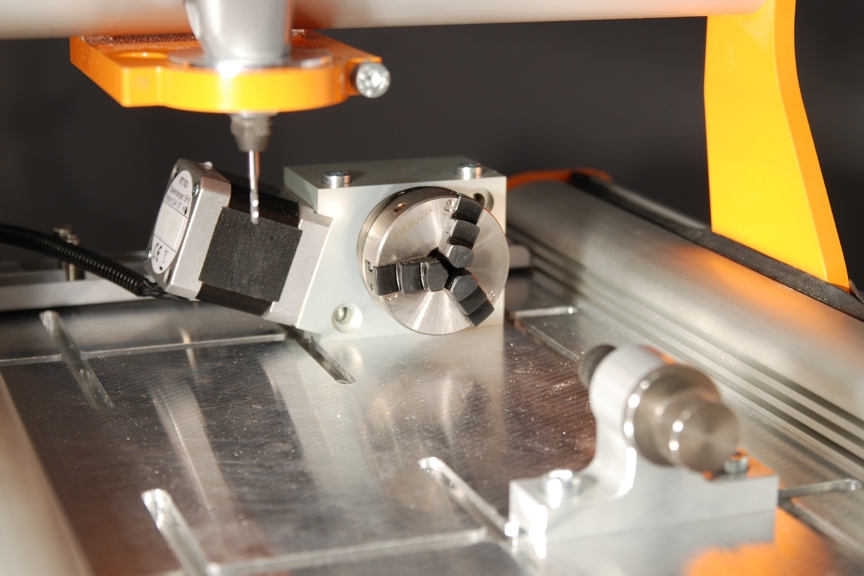
However, making the 4th Axis work requires CAM software that is capable of handling this feature. NOTE: Vectric Cut 2D and Cut 3D will NOT generate GCode for the 4th Axis.
To use the 4th Axis, you have a few options:
OPTION #1 – Manual Indexing.
With the 4th Axis connected, you can create 2D milling files for each side of your stock. For example, if you plan to mill four sides of a block, you can mount the stock in the 4th Axis and set the first side as 0 degrees. You can run the 2D file that is associate with that side. Once that file is complete, you can manually rotate the 4th Axis using UCCNC to the next side; example, 90 degrees. Then you can run the next 2D file. You can continue this process until you have milled all sides.
While this option is not as slick as a fully automated 4 axis milling setup, you can do this with Vectric Cut 2D and UCCNC that comes with your Stepcraft-2 machine. So there is nothing else you need to buy. This way, however, does require more planning and patience.
OPTION #2 – Using Vectric VCarve Pro’s Wrapping Functionality
You can purchase a copy of Vectric VCarve Pro, which has a Wrapping function that will take a 2D pattern and using the software you can convert that into a 4-axis milling operation. This is NOT a full-blown 4-axis setup, but it will index the part automatically to create the finished milled part.
For more information on VCarve Pro’s 4th axis Wrapping functionality, please see the following links:
http://www.222artisans.com/Rotary/RotaryYaxis.html
http://humblesticks.com/cnc-rotary-tutorial.html
http://www.vectric.com/support/gadgets.html
To Purchase VCarve Pro, Click HERE ($699 USD)
In UCCNC you may need to reverse the A axis direction for the milling to come out properly. See the instructions on how to do so here: http://www.stepcraftsupport.com/faq-items/reversing-4th-axis-direction-in-uccnc/
OPTION #3 – For Full 4-Axis Milling Work – use DeskProto
You can turn the Stepcraft-2 machine into a full-on 4 axis mill, but you need a CAM program that is specific to this type of milling operation. We recommend DeskProto (www.deskproto.com). They have a Multi-Axis version http://deskproto.com/products/multiax-ed.php. It is not cheap, costing 995 Euros (around $1090.00 USD), but it is the best and least expensive solution for full 4 axis milling. Please see their site for more information.
- Slotted screwdriver 3 mm
- Allen wrench 1,5, 2,0, 2,5, 3,0, 4,0 and 5,0 mm
both ball ended and also square ended is ideal. - 7 mm and 8 mm wrench
- Long-nose pliers
- Vernier Callipers helps – but a metal ruler can suffice
- Scalpel / Stanley blade / Knife of some sort.
- Good degreaser (rubbing alcohol or nail polish remover works great) its important to degrease all surfaces before applying any decals / adhesive covers. When greasing the ballscrew and slides – grease can prevent decals and adhesive covers from sticking.
- Containers and assorted boxes to organise all the parts in prior to commencing the build.
- Large clean clutter free table.
- An afternoon’s worth of time and patience.
You do not need any CNC machine experience or major technical ability to build the machine. They have been designed to be built by the end user. The fully illustrated instructions (see here) document every step of the kit (see here)
The manual includes many build videos to assist with specific assembly steps. (view here)
There is a growing number of Stepcraft users online in Stepcraft’s forum as well as in various Facebook groups that can help provide support.
Stepcraft also launched stepcraftsupport.com and a new ticket system which you can be sure your support questions get into the hands of an experienced tech quickly. To use this system, simply email your question to support@stepcraft.us
YES! The new Stepcraft-2 210 machine was designed for small milling projects, such as PC boards. This machine retains the Stepcraft V1 design and parts, therefore all parts will remain supported for V1 systems.

If you get this message when you start UCCNC, please read below.
This is a very common occurrence for first-time Stepcraft customers. There are a couple things to check:
1) Do you have a UC100 interface plugged into the parallel port on the back of the Stepcraft-2 machine and into the computer running UCCNC?
If not, you will need to make sure that is plugged in.
2) I do have the UC100 plugged in, but I still get the Demo message.
Did you get an email from Stepcraft with the UCCNC license file?
If not, please send an email to support@stepcraft.us with the serial number on the top of the UC100 controller and we will email you the license code (For verified Stepcraft customers only!)
If you did, are you sure you put the license file in the C:\UCCNC folder as per the instruction manual?
Many times this error will come up because UCCNC can not verify a UC100 interface with a matching license file.
Please download and read this Tech Bulletin (UCCNC STILL IN DEMO MODE)
If you are still experiencing errors, please email us at support@stepcraft.us.
All Stepcraft 2 machines are coming with UCCNC software. This program required a special parallel to USB interface (called a UC100) that is serialized to a license file that you will use when you install the software. In order to use this interface, we need to ship the machine with the parallel card.
Don’t worry, you do not need a parallel interface on your computer (which most modern computers and laptops don’t have). You simply plug the UC100 into the parallel port on the Stepcraft-2 machine and then plug the included USB cable into your computer.
-
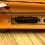
- This is the parallel port on the back of the Stepcraft-2 machine.

-
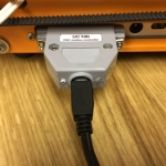
- This is the UC100 Parallel to USB interface installed on the parallel port with a mini USB cable that attaches to your computer.

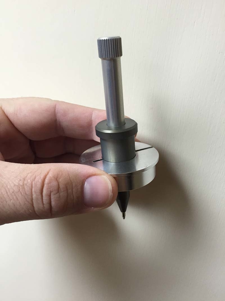
This is common because we work with very close tolarances. If this happens to you, please use a flat head screwdriver and slide in the slot on the adapter and gently twist. This will slightly open the adapter and allow the Pen Plotter to slide into the holder much easier. Be careful not to put too much pressure on it, you just need a slight amount to get it to fit.
-
- The tolarances that we work with are very precise and as such sometimes the 20mm adapter for the Pen Plotter will be too tight for the unit to slide in.
-
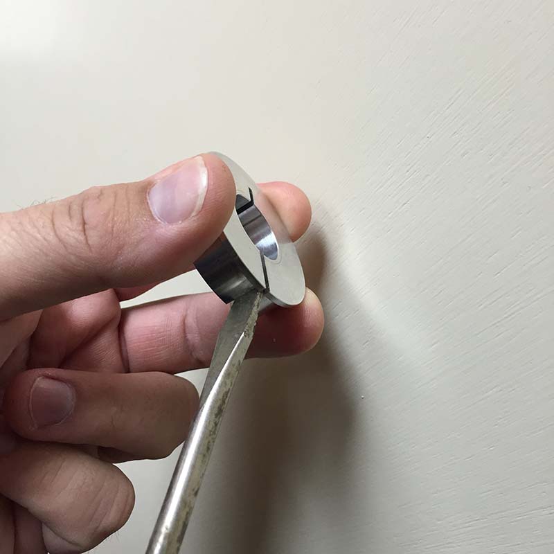
- Using a flat blade screwdriver, you can gently put a little pressure into the slot to open up the center hole. NOTE: Only put a tiny amount of pressure as you will not need a lot to get it to fit.
-
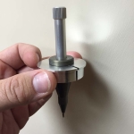
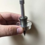
- The Pen Plotter should be able to freely slide into the holder.

-
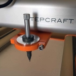
- Here is the Pen Plotter installed in the Stepcraft machine.

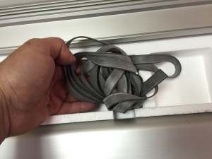 The seal profile is part number 23 in the manual. This is the rubber gasket that is installed on the sides of the machine. The job of the seal profile is to prevent dust and debris from getting into the Y Axis lead screws. There is a predetermined length of seal profile material in your machine’s box. You will need to cut it to the proper length according to the manual.