
The Tool Length sensor is a great addition to your Stepcraft 2 machine, saving time in zeroing the Z axis. There are a few steps to getting the sensor installed and configured properly.
1. Connecting to the mainboard:
Remove the Rubber plug on the front end plate of the machine and run wires inward through the chassis. Run the wires along the channel and through the grommet the X and Z wires are run. Connect the sensor wires to the mainboard in the two open positions between the emergency stop switch wiring and the X/Z end switch (Refer to the manual section 9.6.) Leave enough slack to be able to move the sensor throughout the work area.
2. Replacing the Macro file:
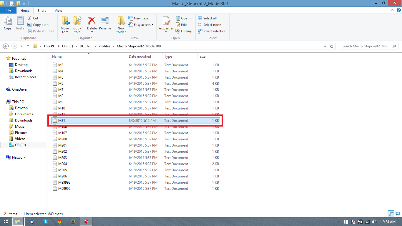
UCCNC needs instructions to be able to properly use the sensor. Download the replacement M31.txt file (listed below) to the machine profile macro folder. For example for a Stepcraft 2 Model 300 the folder is C:\UCCNC\Profiles\Macro_Stepcraft2_Model300 If you have a 3D printing head and plan to use the sensor with that as well make sure to copy to the 3D profile folder as well. You will need move the existing file first as it is set to read only and will not let you successfully copy the file otherwise.
Download the latest macro file here: M31.TXT – Right click and save file. Save as M31.txt
*Note: Opening the M31.txt will allow you to fine tune the height based on personal preference. Edit the newZ value (default 33) adding to the value to lower the Zero height. Since the setup will be separate for the 3D printer profile, you may want the print head slightly higher for 3d printing to avoid dragging.
3. UCCNC Setup:
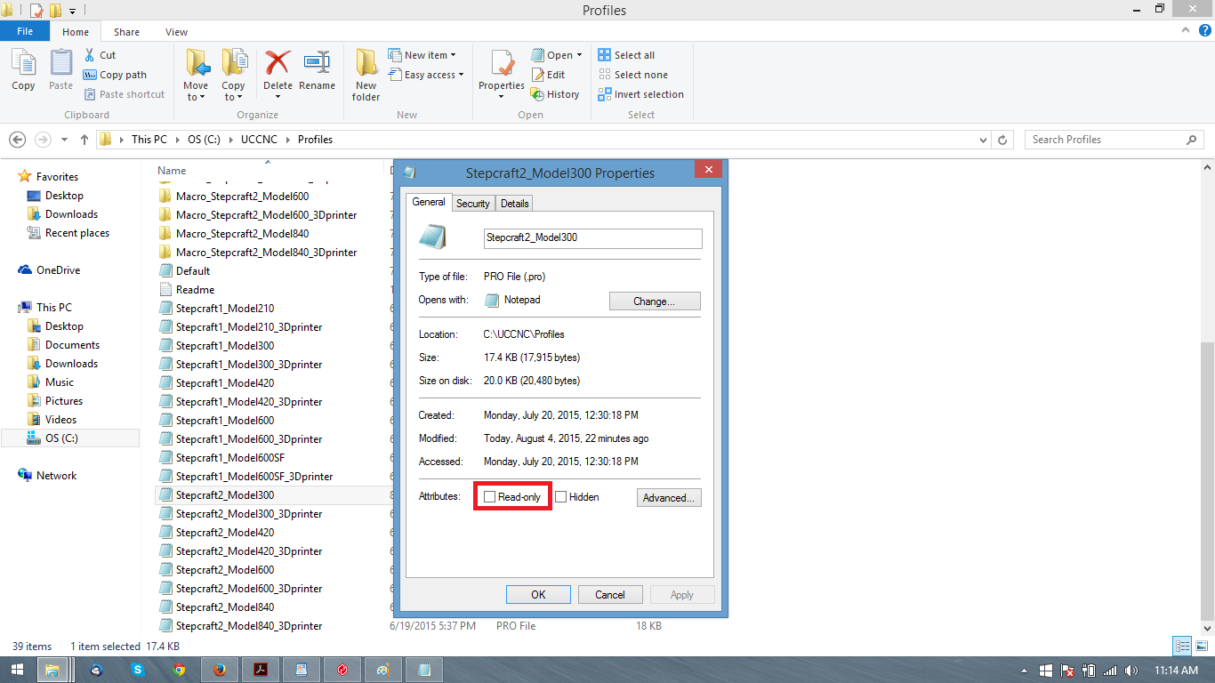
Now we need to edit the profile for the machine so that it knows the tool sensor is connected. In the is C:\UCCNC\Profiles\ find the .PRO file for your machine. First right click on it and choose properties. On the properties box there will be an option for read only, make sure that box is not checked. Click apply and close the window. Now when you change the setting in UCCNC it will be able to save and be stored for each time you open UCCNC.
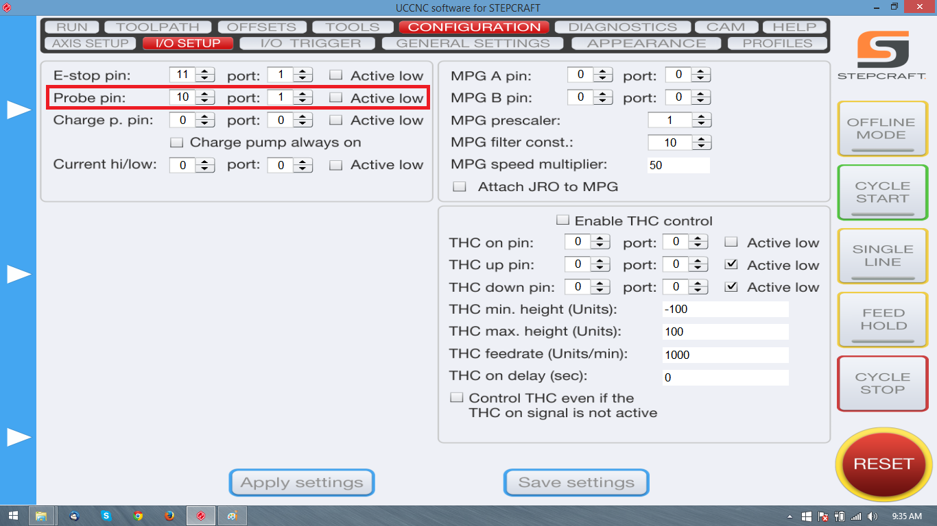
Go to the configuration tab and I/O setup from there. You will see the choice for “Probe pin:” change that to 10, and “Port:” to 1. At the bottom of the page click Apply settings, and then Save Settings.
4. Verify switch function and setup:
Almost there, to verify the switch is operational and that it is properly configured open UCCNC click on the diagnostics tab. Press the sensor switch directly and you should see I10 and Probe light up in green. I10 is showing that the switch is working and Probe is showing that it is correctly configured.

5. Using the sensor:
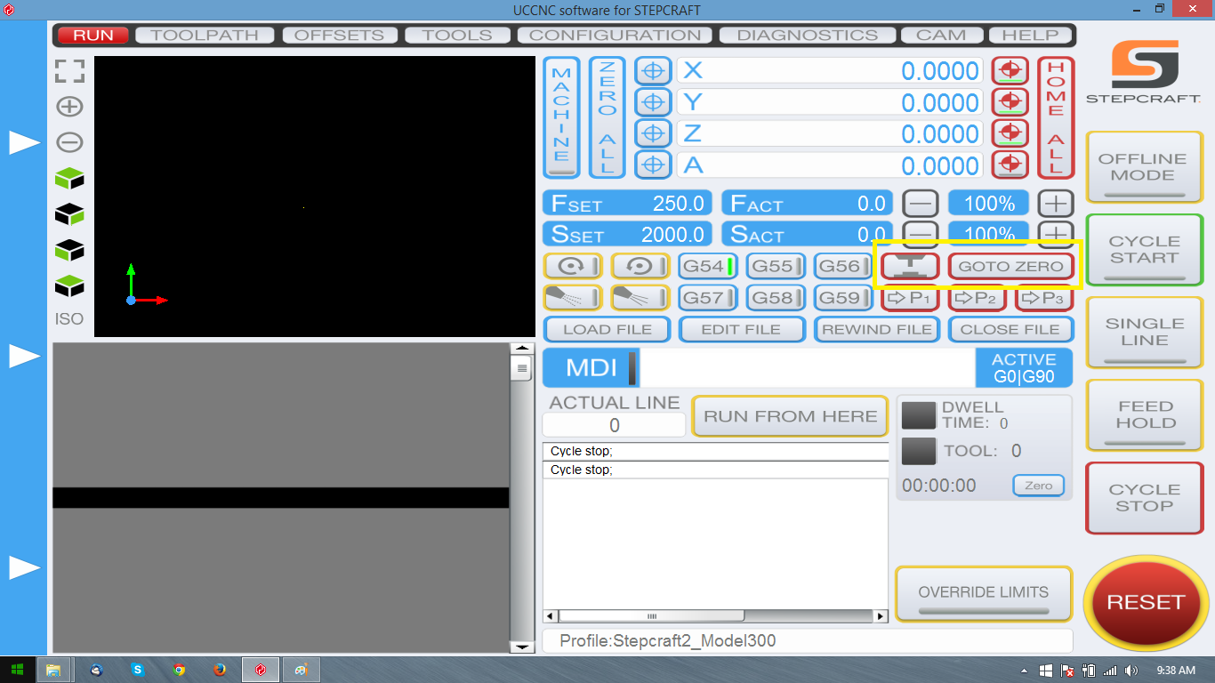
After homing your machine setup your machine with some test material and place the sensor on top. Move the axis over the sensor and zero all. Now press the tool probe button from the main screen. The Z axis will lower slowly until it contacts the sensor. It will then retract and calculate the Z zero taking into account the height of the sensor. Move the sensor out of the way and you can now click Go to Zero. The Z axis will lower to the calculated height for the work material.
This is great. I’d like to see this combined with a manual tool change. I see it being done on this video but there is no more information supplied.
https://www.youtube.com/watch?v=Z0QyOS9BarM
thanks, jim
It can be done by rewriting the macro with the extra commands. In the video description he mentions it taking ages to write and get everything working correct. It is something we are working on.