Working with Stepcraft machine you have two values the machine coordinates and the work-piece coordinates. The machine coordinates are the machine in the physical range of motion for the machine. When you perform the “Home All” when opening UCCNC it is doing this so UCCNC knows the location of the machine and controls it correctly. One item to note is the Y axis homes in reverse, so when the homing procedure completes the machine is at the upper limit of the Y axis. This is why it is required to have the correct machine profile loaded when running UCCNC
The images below show the difference in homing and moving the machine to X Y Z zero.
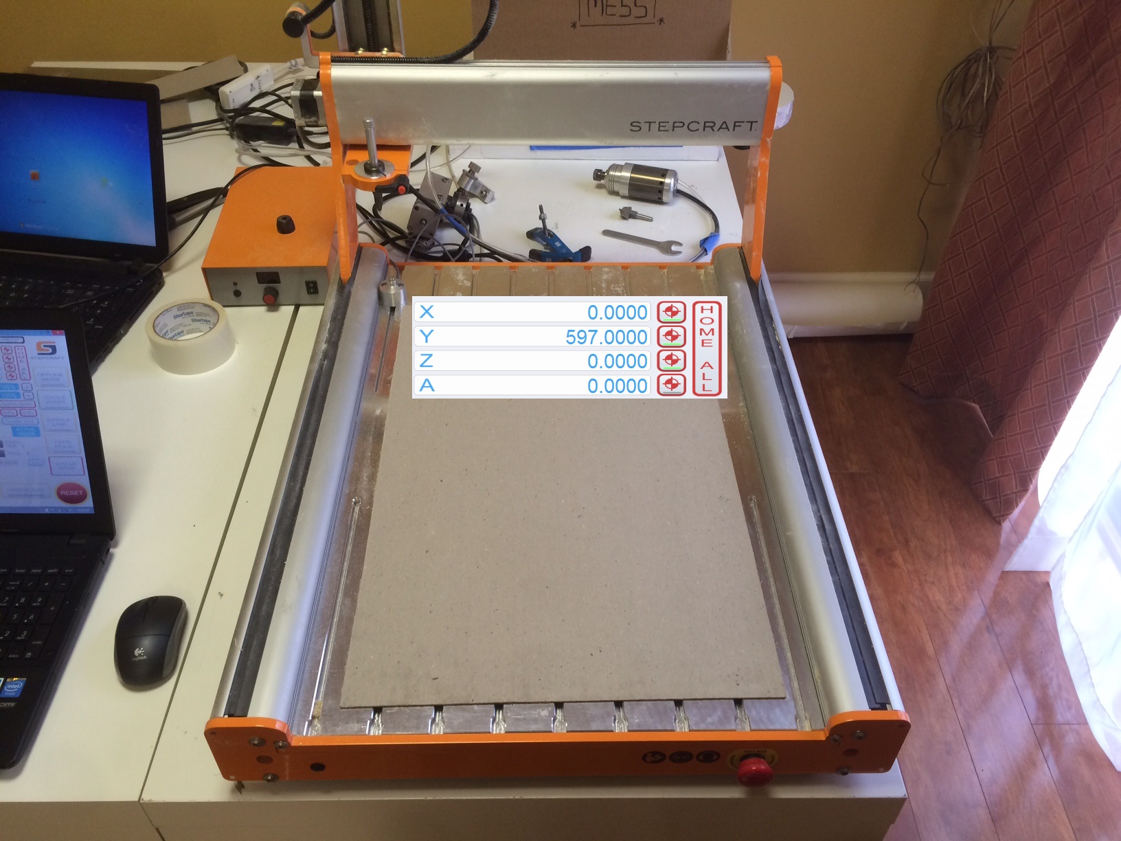
(Shown on a Stepcraft 600, the value will vary with your machine size)
This is with the machine at full zero.
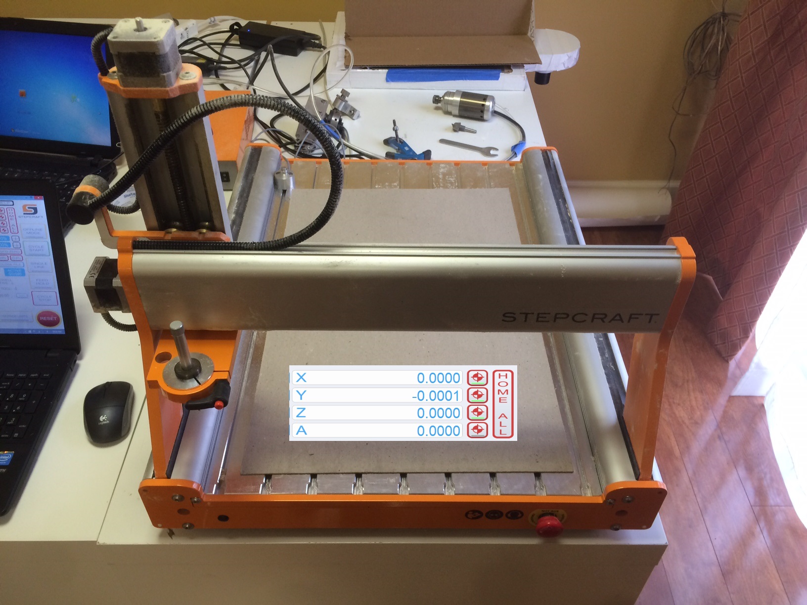
At this point moving the X axis to the right is X+, moving Y axis towards the back of the machine is Y+, and moving Z axis down is Z+
Familiarize yourself with this orientation of the machine. When you set up a project in your CAM software one of the choices will be the XY Datum Position or more commonly referred to as the start point. This is set so that when you start to machine your project you know it is starting in the correct spot. Depending on what your work piece is and how it is clamped to the table may sometimes cause you to change this.
For the examples here I have the start point set at the common lower left point.
Now the work-piece coordinates are set when you have a project ready. They are set by the blue zero buttons and the zero all button. When these are set UCCNC now knows where it needs to start. It will stop a job from starting if the job would run outside of the limits of the machine. If I am cutting something 10 inches wide on this model 600 I need to zero my X axis far enough to the left to allow the machine to safely travel 10 inches to the right. Same goes for the Y axis, if I try to set it too far back UCCNC will not allow the job to start because it knows it will run out of its limit. The Z axis also has an option for a start point and in most cases will be the top of the work piece. Make sure if you are opening a file someone sent that you know which Z origin is set. The axis can be zeroed individually or with the zero all. Generally I would move the machine to the proper X and Y locations then move the Z axis down and choose Zero All. Sometimes you may only need to change one of the start points, for example if you wanted to make another piece right next to the original you would only change the X zero.
In this image created a project of 10 inches by 10 inches and drew out the origin point and note on the X and Y zero. The full outline of the box shows what the “imaginary” blank slate of a 10×10 project actually looks like.

Now without changing the zero settings in UCCNC, I created a blank 10×10 project in Cut2D and added a Volkswagen logo to it. I used the center in workpiece option (F9 shortcut) to center the logo.
Now to run the project and see the results.

You’ll see in the image that it came out correctly as it was designed in Cut2D. The display is slightly different in UCCNC as it cuts off the excess in the display. Once a file is loaded in UCCNC and the zero point set a yellow dot will appear and show at the set start point. Manually jogging the machine the dot will move. This is useful to verify that the machine will not potentially hit any clamps or other obstructions that might be present. You can also use to this to make sure the material is going to cut where you want it to.
Knowing the project is where it should be you should be all set to choose “Cycle Start” and have a successful run.
Leave A Comment